Programming an ATtiny85, Part 1: Using C with a USBtinyISP Arduinos are great for prototyping, but for a small, low-power, cheap and simple design, an ATtiny chip seems like just the ticket. For just a few dollars you can do most of what you could with an Arduino and use a lot of the same code, as long as you can make do with a little less memory and fewer pins. I've been wanting to try them, and recently I ordered a few ATtiny85 chips. There are quite a few ways to program them. You can buy programmers specifically intended for an ATtiny, but I already had a USBtinyISP, a chip used to program Arduino bootloaders, so that's what I'll discuss here. Wiring to the USBtinyISP The best reference I found on wiring was Using USBTinyISP to program ATTiny45 and ATTiny85. That's pretty clear, but I made my own Fritzing diagram, with colors, so it'll be easy to reconstruct it next time I need it. The colors I used: MISO yellow VCC red SCK white MOSI green RESET orangeor red/black GND black Programming the ATtiny in C I found a couple of blink examples at electronut.in, Getting Started with ATtiny AVR programming, and in a Stack Exchange thread, How to program an AVR chip in Linux Here's some basic blink code: #include <avr/io.h> #include <util/delay.h> int main (void) { // Set Data Direction to output on port B, pins 2 and 3: DDRB = 0b00001000; while (1) { // set PB3 high PORTB = 0b00001000; _delay_ms(500); // set PB3 low PORTB = 0b00000000; _delay_ms(500); } return 1; } Then you need a Makefile. I started with the one linked from the electronut page above. Modify it if you're using a programmer other than a USBtinyISP. make builds the program, and make install loads it to the ATtiny. And, incredibly, my light started blinking, the first time! Encouraged, I added another LED to make sure I understood. The ATtiny85 has six pins you can use (the other two are power and ground). The pin numbers correspond to the bits in DDRB and PORTB: my LED was on PB3. I added another LED on PB2 and made it alternate with the first one: DDRB = 0b00001100; [ ... ] // set PB3 high, PB2 low PORTB = 0b00001000; _delay_ms(500); // set PB3 low, PB2 high PORTB = 0b00000100; _delay_ms(500); Timing Woes But wait -- not everything was rosy. I was calling _delay_ms(500), but it was waiting a lot longer than half a second between flashes. What was wrong? For some reason, a lot of ATtiny sample code on the web assumes the chip is running at 8MHz. The chip's internal oscillator is indeed 8MHz (though you can also run it with an external crystal at various speeds) -- but its default mode uses that oscillator in "divide by eight" mode, meaning its actual clock rate is 1MHz. But Makefiles you'll find on the web don't take that into account (maybe because they're all copied from the same original source). So, for instance, the Makefile I got from electronut has CLOCK = 8000000 If I changed that to CLOCK = 1000000 now my delays were proper milliseconds, as I'd specified. Here's my working attiny85 blink Makefile. In case you're curious about clock rate, it's specified by what are called fuses, which sound permanent but aren't: they hold their values when the chip loses power, but you can set them over and over. You can read the current fuse settings like this: avrdude -c usbtiny -p attiny85 -U lfuse:r:-:i -v which should print something like this: avrdude: safemode: hfuse reads as DF avrdude: safemode: efuse reads as FF avrdude: safemode: Fuses OK (E:FF, H:DF, L:62) To figure out what that means, go to the Fuse calculator, scroll down to Current settings and enter the three values you got from avrdude (E, H and L correspond to Extended, High and Low). Then scroll up to Feature configuration to see what the fuse settings correspond to. In my case it was Int. RC Osc. 8 Mhz; Start-up time PWRDWN/RESET; 6CK/14CK+ 64ms; [CKSEL=1011 SUT=10]; default value and Divide clock by 8 internally; [CKDIV8=0] was checked. More on ports and pins There's more info on ATtiny ports in ATTiny Port Manipulation (Part 1): PinMode() and DigitalWrite() Nobody seems to have written much about AVR/ATTINY programming in general. Symbols like PORTB and functions like _delay_ms() come from files in /usr/lib/avr/include/, at least on my Debian system. There's not much there, so if you want library functions to handle nontrivial hardware, you'll have to write them or find them somewhere else. As for understanding pins, you're supposed to go to the datasheet and read it through, all 234 pages. Hint: for understanding basics of reading from and writing to ports, speed forward to section 10, I/O Ports. A short excerpt from that section: Three I/O memory address locations are allocated for each port, one each for the Data Register - PORTx, Data Direction Register - DDRx, and the Port Input Pins - PINx. The Port Input Pins I/O location is read only, while the Data Register and the Data Direction Register are read/write. However, writing a logic one to a bit in the PINx Register, (comma sic) will result in a toggle in the corresponding Data Register. In addition, the Pull-up Disable - PUD bit in MCUCR disables the pull-up function for all pins in all ports when set. There's also some interesting information there about built-in pull-up resistors and how to activate or deactivate them. That's helpful, but here's the part I wish they'd said: PORTB (along with DDRB and PINB) represents all six pins. (Why B? Is there a PORTA? Not as far as I can tell; at least, no PORTA is mentioned in the datasheet.) There are six output pins, corresponding to the six pins on the chip that are not power or ground. Set the bits in DDRB and PORTB to correspond to the pins you want to set. So if you want to use pins 0 through 3 for output, do this: DDRB = 0b00001111; If you want to set logical pins 1 and 3 (corresponding to pins 6 and 2 on the chip) high, and the rest of the pins low, do this: PORTB = 0b00001010; To read from pins, use PINB. In addition to basic functionality, all the pins have specialized uses, like timers, SPI, ADC and even temperature measurement (see the diagram above). The datasheet goes into more detail about how to get into some of those specialized modes. But a lot of those specialties are easier to deal with using libraries. And there are a lot more libraries available for the Arduino C++ environment than there are for a bare ATtiny using C. So the next step is to program the ATtiny using Arduino ... which deserves its own article. Tags: hardware, arduino, programming [ 18:01 Nov 02, 2017 More hardware | permalink to this entry | ]
This is one of my news digests. If you like my editorial choices, there are more to be found by clicking on the "dear reader" link, and on my name above. Enjoy !
Takeoff projects help students complete their academic projects. Register at takeoff projects today to find and learn about different interesting big data projects and grab the best jobs. Get started right now.
Running any of the Raspberry Projects from my website assumed you have have certain libraries installed on your Pi, such as GLM, Bullet and Assimp.. This is a quick explination of how to get those libs on your Pi so that you can build all the downloaded projects.
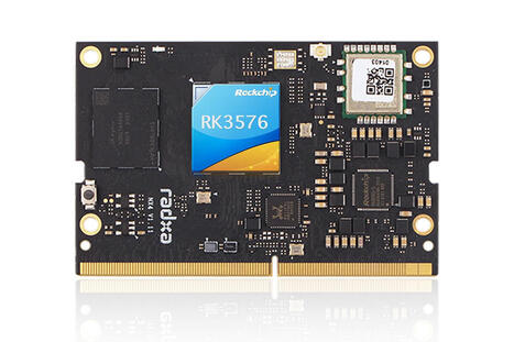
Radxa NX4 is a 260-pin SO-DIMM SoM built around the Rockchip RK3576(J) octa-core Cortex-A72/A53 industrial SoC with a 6 TOPS NPU for edge AI workloads.It...
Video ini berisi simulasi termometer digital berbasis Arduino Uno dengan sensor suhu LM35 menggunakan aplikasi Tinkercad. Simulasi ini dibuat sebagai bagian dari tugas Ujian Akhir Semester (UAS) mata kuliah Embedded System. Data suhu dibaca oleh sensor LM35, diproses oleh Arduino Uno, dan hasilnya ditampilkan pada LCD 16x2.
Komponen yang digunakan meliputi Arduino Uno, sensor LM35, LCD 16x2, potensiometer, breadboard, dan kabel jumper.
Video ini bertujuan untuk menunjukkan bahwa rangkaian dan program sistem embedded dapat berjalan dengan baik sesuai perancangan.
Welcome to our channel! Before we dive into the details of the Raspberry Pi 3 A+ Computer Board, please note that the link to purchase this product at a discounted price is pinned in the first comment below. This compact single-board computer is a versatile tool that brings desktop-level capabilities to a small, affordable package. Powered by a 64-bit quad-core processor running at 1.4GHz, the Raspberry Pi 3 A+ can handle everyday tasks such as spreadsheets, word processing, and even high-definition video playback with ease. It supports several flavors of Linux, making it an excellent choice for hobbyists, educators, and developers alike. One of its standout features is the dual-band wireless LAN (2.4GHz and 5GHz), which ensures stable and fast internet connectivity, alongside Bluetooth 4.2/BLE for connecting peripherals wirelessly.
This board is especially popular in educational settings, helping kids and beginners learn programming and computer science fundamentals. Its compact form factor and low power consumption make it ideal for embedded projects, DIY electronics, and portable computing setups.
Pros of the Raspberry Pi 3 A+ include its powerful yet energy-efficient processor, dual-band Wi-Fi, Bluetooth support, and broad Linux compatibility. It comes fully assembled and tested, making it accessible even to those new to single-board computers. On the downside, it has fewer USB ports compared to some other Raspberry Pi models, and the RAM is limited to 512MB, which might restrict performance for more demanding applications.
Overall, the Raspberry Pi 3 A+ offers great value for anyone looking to explore Linux computing, programming education, or compact computing projects. Don't forget, the discounted purchase link is pinned in the first comment for your convenience. Check it out to get started with this powerful little board today!
La programmation Arduino est une forme de programmation embarquée utilisant le langage C/C++. Elle repose sur une architecture sans système d’exploitation, où le microcontrôleur exécute en permanence une boucle principale. Cette programmation permet la gestion des entrées/sorties, la temporisation et la réaction aux événements matériels en temps réel.
How to Connect Raspberry Pi to Wifi Using Terminal (easy Method) | 🔒 Surfshark VPN Deal — Stay private and secure. $1.99/mo + 3 Months Free ▸ https://theslopfarm.com/Surfshark
Discover the simple steps to connect your Raspberry Pi to Wi-Fi using just a terminal. This guide is perfect for beginners and tech enthusiastm who want an easy method without complex tools or software.
✈️ Trip.com – Travel Deals Compare cheap flights, hotels, and vacation packages across 200+ countries with Trip.com — earn Trip Coins for every booking. ▸ https://theslopfarm.com/trip
💵 Shopify – $1 Dropshipping Offer Start free, then pay just $1 for your first month on Shopify! Launch your store, test products, and enjoy 25% off annual plans — everything you need to sell, ship, and scale. ▸ https://theslopfarm.com/shopify
🧢 Fanatics – Official Sports Apparel Rep your favorite team with official sports gear from Fanatics — licensed NFL, NBA, MLB, and college merch on sale now. ▸ https://theslopfarm.com/fanatics
🎮 Green Man Gaming – Gaming Deals Save up to 80% on PC games and Steam keys from Green Man Gaming — instant delivery and trusted publisher deals. ▸ https://theslopfarm.com/gamingdeals
🌐 Bluehost – Hosting from $3.99/mo Get web hosting starting at just $3.99/month with Bluehost — includes a FREE domain for your first year and 30-day money-back guarantee. Perfect for WordPress with 24/7 expert support. ▸ https://theslopfarm.com/bluehost
📈 Helium 10 – Amazon Seller Tools Get 20% off your first 6 months (or 10% off for life) on Helium 10 — the ultimate tool suite for Amazon & Walmart sellers. Includes product research, keyword tracking, and listing optimization — plus a 7-day money-back guarantee. ▸ https://theslopfarm.com/helium10
🔒 Surfshark VPN – $1.99 Privacy Deal Get secure, lightning-fast VPN protection for just $1.99/month — plus 3 extra months free! Hide your IP, mask your email, block trackers, and browse safely on every device with Surfshark’s top-rated privacy tools. ▸ https://theslopfarm.com/Surfshark
Affiliate Disclosure: Some links may be affiliate links. We may earn a commission at no extra cost to you, which helps keep the content coming!
Raspberry Pi, Wi-Fi connection, terminal command, connecting Raspberry Pi, Easy Method, setup Wi-Fi on Raspberry Pi, network configuration for Raspberry Pi, access internet with Raspberry Pi, wireless setup terminal guide, Raspberry Pi networking
Disclaimer: Content is for informational and entertainment purposes only. No guarantee of accuracy or timeliness. Not professional advice. Use at your own risk.
Engineering information and connections for the global community of engineers. Find engineering webinars, research, articles, games, videos, jobs and calculators.
RasTech Raspberry Pi 5 Kit 16GB RAM with 27W PD Power Supply 5.1V5A,Heat Sinks and Ras...
Welcome to our channel! Before we dive into the detailed review of the RasTech Raspberry Pi 5 Kit with 16GB RAM, just a quick note: the link to purchase this product at a discounted price is pinned in the first comment, so be sure to check it out. This kit is a comprehensive package designed for both hobbyists and professionals who want to harness the power of the latest Raspberry Pi 5 board. Included in the kit is the Raspberry Pi 5 single board computer with a hefty 16GB of RAM, a robust 27W GaN power supply rated at 5.1V and 5A, four heat sinks to keep the system cool, and a screwdriver for easy assembly.
The Raspberry Pi 5 itself is a significant upgrade over its predecessor, featuring a Broadcom BCM2712 64-bit quad-core Arm Cortex-A76 processor clocked at 2.4GHz. This translates to roughly 2 to 3 times faster CPU performance compared to the Raspberry Pi 4, which is a major boost for multitasking, programming, and media applications. On the graphics side, the 800MHz VideoCore VII GPU supports OpenGL ES 3.1 and Vulkan 1.2, delivering enhanced graphical performance suitable for gaming, media streaming, and more.
One of the standout features of this kit is the high-quality power solution. The included 27W GaN power supply ensures stable and sufficient current delivery even under full load, eliminating the common low-voltage issues seen in less capable adapters. This means you can push the Raspberry Pi 5 to its limits without worrying about power instability.
Connectivity options are impressive: dual micro HDMI ports support dual 4Kp60 displays with HDR, enabling a stunning visual experience for workstations or media centers. The board includes two USB 3.0 ports and two USB 2.0 ports, tripling bandwidth compared to previous models and supporting multiple peripherals simultaneously. Gigabit Ethernet, dual-band Wi-Fi, and Bluetooth 5.0/BLE round out the connectivity suite, making this Raspberry Pi 5 kit versatile for networking and IoT projects. Additionally, the PCI Express 2.0 x1 slot opens up possibilities for SSD expansion (with a separate M.2 HAT), which is a first for Raspberry Pi boards.
The kit also includes four heat sinks to help maintain optimal temperatures during heavy use, and a screwdriver for easy installation. Backed by a 12-month warranty and lifetime service with prompt customer support, this kit offers peace of mind alongside performance.
Pros: - Powerful 16GB RAM and quad-core 2.4GHz CPU for high performance - Advanced GPU supporting modern graphics APIs - Stable 27W GaN power supply preventing voltage drops - Dual 4Kp60 HDR display support via micro HDMI - Extensive connectivity including USB 3.0, Gigabit Ethernet, Wi-Fi, Bluetooth - PCIe slot for SSD expansion - Cooling solution with heat sinks included - Warranty and responsive customer service
Cons: - PCIe SSD expansion requires additional hardware - Premium price point compared to lower RAM models - May be overkill for casual Raspberry Pi users
Overall, the RasTech Raspberry Pi 5 Kit 16GB RAM is a top-tier offering that combines powerful hardware, excellent connectivity, and solid build quality. Whether you're building a media server, a development workstation, or experimenting with embedded projects, this kit is a worthy investment. Remember, the link to get this product at a discount is pinned in the first comment, so don’t miss out on that offer. Check it out now!
In this video, I have created a mini Dinosaur Game using an ESP8266 NodeMCU and an OLED display, inspired by the Chrome offline dinosaur game.
This DIY electronics and Arduino project uses: - ESP8266 NodeMCU microcontroller - 0.96 inch OLED display (SSD1306) - Push button for jump control - Arduino IDE and Adafruit libraries
The game includes jumping physics, obstacles (cactus), score system and game over screen. It is a perfect beginner to intermediate level embedded systems and IoT project.
If you are learning Arduino, ESP8266, or embedded programming, this project will help you understand: - I2C communication with OLED - Button input handling - Game logic and collision detection - Graphics drawing on OLED using Adafruit GFX
This project is great for school projects, science fairs, engineering students and hobbyists.
Finished Latest MMDVM Hotspot + Raspberry pi zero W +3.2 inch LCD +Antenna + 16G SD card + metal Case P25 DMR YSF Buy on : https://s.click.aliexpress.com/e/_c3JTMrWF ==========================================================
Stay Connected:
Like this video if you enjoyed it!
Subscribe for more reviews and top product picks. Finished Latest MMDVM Hotspot + Raspberry pi zero W +3.2 inch LCD +Antenna + 16G SD card + metal Case P25 DMR YSF
Turn on notifications so you don’t miss a thing.
Got questions or ideas for new reviews? Drop us a comment below!
Topics We Cover Finished Latest MMDVM Hotspot + Raspberry pi zero W +3.2 inch LCD +Antenna + 16G SD card + metal Case P25 DMR YSF
Disclaimer
Heads up: The info in this video is just for fun and learning! We’re not responsible for any issues arising from installing Finished Latest MMDVM Hotspot + Raspberry pi zero W +3.2 inch LCD +Antenna + 16G SD card + metal Case P25 DMR YSF or using products like the ANBERNIC RG406H RG 406H Handheld Game Console 4inch IPS Multi-touch Screen Retro Video Gam. Always check the manufacturer’s instructions to avoid potential hazards. Finished Latest MMDVM Hotspot + Raspberry pi zero W +3.2 inch LCD +Antenna + 16G SD card + metal Case P25 DMR YSF
This video may include affiliate links. If you make a purchase, we might earn a small commission at no extra cost to you.
Play it safe, and if you need help with installation, don’t hesitate to ask a professional! Finished Latest MMDVM Hotspot + Raspberry pi zero W +3.2 inch LCD +Antenna + 16G SD card + metal Case P25 DMR YSF
Electronics seekh rahe ho? ⚡ Is 3D YouTube Short me humne basic electronic components ke units ko simple Hindi me samjhaya hai. Is video me aap seekhenge 👇 🔹 Resistor ki unit – Ohm (Ω) 🔹 Capacitor ki unit – Farad (F) 🔹 Inductor ki unit – Henry (H) 🔹 Diode aur LED ke units 🔹 Battery voltage – Volt (V) 🔹 Power – Watt (W) 🔹 Frequency – Hertz (Hz) Yeh video students, beginners, ITI, Diploma, Engineering aur Arduino learners ke liye perfect hai. Agar aap Electronics basics se advance tak seekhna chahte ho, to channel ko follow / subscribe zaroor karo 🔔
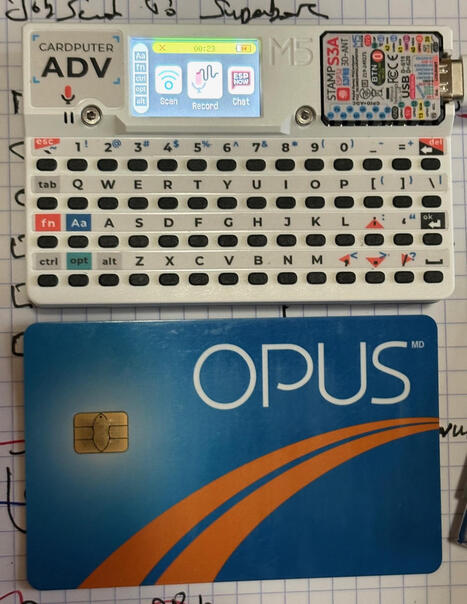
Évidemment vous connaissez probablement Arduino, peut-être Raspberry Pi, mais connaissez-vous le Cardputer?!? Occupant la surface d'une carte de crédit, et évidemment bien plus épais, c'est comme un...
Latest Raspberry Pi 4 Model B 8GB RAM Raspberry Pi 4 1.2 version BCM2711 Quad core Cortex-A72 ARM v8 1.5GHz Buy on : https://s.click.aliexpress.com/e/_c2Ru2XgX ==========================================================
Stay Connected:
Subscribe and never miss trending online deals!
Subscribe for more reviews and top product picks. Latest Raspberry Pi 4 Model B 8GB RAM Raspberry Pi 4 1.2 version BCM2711 Quad core Cortex-A72 ARM v8 1.5GHz
Turn on notifications so you don't miss a thing.
Got questions or ideas for new reviews? Drop us a comment below!
Topics We Cover Latest Raspberry Pi 4 Model B 8GB RAM Raspberry Pi 4 1.2 version BCM2711 Quad core Cortex-A72 ARM v8 1.5GHz
Disclaimer
Heads up: The info in this video is just for fun and learning! We're not responsible for any issues arising from installing Latest Raspberry Pi 4 Model B 8GB RAM Raspberry Pi 4 1.2 version BCM2711 Quad core Cortex-A72 ARM v8 1.5GHz or using products like the ANBERNIC RG406H RG 406H Handheld Game Console 4inch IPS Multi-touch Screen Retro Video Gam. Always check the manufacturer's instructions to avoid potential hazards. Latest Raspberry Pi 4 Model B 8GB RAM Raspberry Pi 4 1.2 version BCM2711 Quad core Cortex-A72 ARM v8 1.5GHz
This video may include affiliate links. If you make a purchase, we might earn a small commission at no extra cost to you.
Play it safe, and if you need help with installation, don't hesitate to ask a professional! Latest Raspberry Pi 4 Model B 8GB RAM Raspberry Pi 4 1.2 version BCM2711 Quad core Cortex-A72 ARM v8 1.5GHz
SHOP AND SUPPORT! 🎁 ================== Enjoy the videos? Use these links when you shop -- it’s a simple way to support the channel and helps fund future projects! 💖
Comment piloter un moteur triphasé avec un microcontrôleur miniature ? 🚀 Dans ce tutoriel complet, je réponds à la commande d'une entreprise pour programmer un PIC 12F675 afin de gérer l'inversion de sens d'un moteur avec des cycles précis.
Nous allons voir ensemble tout le processus de création : de la rédaction du code sur MikroC à la simulation sur Proteus, jusqu'au test réel sur plaque d'essai (breadboard). Vous découvrirez comment gérer les temps de fonctionnement (30s) et les pauses de sécurité (10s) pour éviter d'endommager le moteur à cause de l'énergie cinétique.
Ce que vous allez apprendre : - Configuration et programmation d'un PIC 12F675 via un programmateur. - Utilisation d'un régulateur 7805 pour protéger votre microcontrôleur (Logique TTL 5V). - Importance des condensateurs de filtrage et de déparasitage (104). - Lecture d'un chronogramme et simulation logicielle avant passage au réel. - Câblage étape par étape sur plaque d'essai.
Chapitres de la vidéo [00:00] : Présentation du projet : Commande moteur triphasé (inversion de sens). [00:24] : Les composants nécessaires : PIC 12F675, régulateur 7805 et protection. [00:55] : Pourquoi le 5V est vital ? Explication de la logique TTL. [02:30] : Analyse du cahier des charges : Temps de cycle (30s / 10s pause). [03:45] : Programmation du PIC : Utilisation du programmateur et logiciel. [05:46] : Simulation sur Proteus : Vérification du programme et chronogramme. [07:37] : Astuce : Programmer plusieurs microcontrôleurs à la suite. [09:22] : Guide pratique : Comment utiliser une plaque à essai (Breadboard). [10:30] : Identification des broches et détrompeur du PIC 12F675. [11:48] : Installation des résistances et test des LED au multimètre. [13:54] : Câblage de l'alimentation (Vcc et GND). [15:21] : Montage du circuit de régulation (7805 + condensateurs). [18:25] : Ajout d'une diode de protection contre l'inversion de polarité. [19:25] : Test réel : Résolution de problème (batterie faible) et validation finale. [21:00] : Conclusion et ressources pour apprendre MikroC et Proteus.
STMicroelectronics' STM32MP21 microprocessor family combines a 1.5 GHz 64-bit Arm Cortex-A35 application core with a 300 MHz 32-bit Arm Cortex-M33 core...
It’s never a bad time to think about saving money, and self-hosting your own software is a great place to start. With the help of my always-on Raspberry Pi, I’m hoping to buck trends and avoid subscriptions by hosting the following projects on my own.
To get content containing either thought or leadership enter:
To get content containing both thought and leadership enter:
To get content containing the expression thought leadership enter:
You can enter several keywords and you can refine them whenever you want. Our suggestion engine uses more signals but entering a few keywords here will rapidly give you great content to curate.


 Your new post is loading...