In the last part of my tutorial about the A4988 driver, I'm going to explain how to build a controller to adjust speed and rotation direction of a stepper motor.

 Your new post is loading...
 Scoop.it! In the last part of my tutorial about the A4988 driver, I'm going to explain how to build a controller to adjust speed and rotation direction of a stepper motor. 
No comment yet.
Sign up to comment
Scoop.it!

Today, I made a small 3x3x3 LED cube with an ATtiny2313 that I had from about 2 weeks ago. Whenever I had to reprogram the LED cube when I thought of more awesome patterns, I had to get out my breadboard and then wire up everything again referring to pin-outs of ATtiny2313 and make sure everything is connected right and then finally upload the new code.
Scoop.it!

Some time ago I started writing about connecting Arduino to cellular network. Using standard GSM AT commands, a program running on Arduino can place and take calls, send and receive SMS, shoot pictures, access the Internet while monitoring phone’s battery level, signal strength and connection status. For many of these tasks any old phone works quite well, however, there are times when a specialized piece of hardware is desired. Today I’m going to talk about one such piece of hardware which can be connected to Arduino board using USB Host Shield.
Scoop.it!

The principle behind this scanner is the typical of a line scanner. A laser beam intercepts the object to be measured and a camera, positioned at a known angle and distance shoots a series of images. With some trigonometry considerations and optic laws it is relatively easy to reconstruct the Zeta dimension, the measurement of the distance between the object and the camera. Commercial systems based on this principle, named line scanner or profilometers, are used in industries and are typically characterized by a high frame rate (even 200 or more frames per second) and a strength suitable for industrial uses. An industrial profilometer price ranges from a few thousand Euros to several tens of thousands of Euros. The cost of the components for the system I propose here does not exceed 100/150 €, if you already have an SLR.
Scoop.it!

I wanted my arm to be portable and independent of big computers and all currently available controllers lack flexibility that I needed, therefore I started building my own controller around Arduino platform. This article shows first preliminary result of this work – inverse kinematics code which would be used to position the arm.
Axel's insight:
A video of the arm in action is available here: http://www.circuitsathome.com/mcu/controlling-robotic-arm-with-arduino-and-usb-mouse
Scoop.it!
Connect Arduino UNO with you camera and create wonderful timelapses - German language The code: http://playground.arduino.cc//Deutsch/TimelapseDe ( based on ...
Scoop.it!

The RFID (Radio frequency identification) technology steps-up in the modern age in the field of access system, identification, protection system and so many places. In this project, we are using this as an door opening as well as door closing system based on the RFID card number identification. This antitheft project is built to secure the house from unwanted accidents.
Scoop.it!
An Open-Source Environmental Monitoring Platform consisting of arduino-compatible hardware, data visualization web API, and mobile app.
Scoop.it!

In conjunction with the release of the new version of the Arduino IDE and the Arduino Robot, we’re also putting out a TCT LCD screen. The screen was developed in conjunction with Complubot and the library relies on the AdafruitGFX and ST7735 libraries.
Scoop.it!

The Arduino RFID lock is a lock that can be opened easily, but is secure. The lock works with a server database that can register card codes. On the door there is a RFID reader connected to the lock. If the RFID reader reads a registered card the door will open. One of the pictures gives a schematic overview of the functionality of the Arduino RFID lock.
Scoop.it!

Jamie & Adam's Tested Arduino: Will's dark pantry has forced him to build a simple, Arduino-controlled LED strip lighting setup--to save his sanity.
Scoop.it!

Make this 5,5 cm tall ATtiny based robot wobble with almost any IR remote.
Put it next to your TV and it shows its happiness each time you use your remote (This way at least someone gets some movement). Or you can have it dance to the signal of your sound system.

AnalysIR's curator insight,
July 6, 2013 6:25 PM
A cute IR remote control
For anyone interested in IR protocols - we have just launched a Crowdfunding campaign on IndieGoGo for AnalysIR - IR Decoder & Analyzer (Arduino & Raspberry Pi). Currently we support 17 IR protocols and are looking for more to add as part of the campaign. Suggestions Welcome!
Scoop.it!

We’re happy to announce the release of a new version of the Arduino software, version 1.0.5. Barring any unexpected bugfixes, this is the final planned release of the 1.0 series of the IDE. Future releases will be from the 1.5 branch that has been in beta since last summer.
|
Scoop.it!

In Super Awesome Sylvia’s latest video, she walks through a build for an Arduino-powered Pulse Sensor pendant necklace. The sensor attaches to your ear and is connected to a pendant around your neck. The LEDs on the pendant blink in pace with your heart. In addition to step-by-step directions for the project, Sylvia offers a short lesson in cardiology 101.
Scoop.it!

A resolution of 8x8 pixels may not sound like enough for anything interesting, but with the right setup, it is possible to create beautiful, complex animations and even add some interactivity.
In the next pages I will detail the steps needed to build the low-res display you see in the video below.
Scoop.it!

This tutorial describes the building of a fake window which is illuminated by superlight LEDs in different colors. These are controlled by an Arduino microcontroller board so that the current daytime is reflected by the light mood.
Scoop.it!

Using only an Arduino, a few resistors, a buzzer, and some bits of aluminum foil, you can create your own touch-sensor piano keyboard in just a few minutes! Using an Arduino Uno, you can create a piano with up to 18 keys; or with an Arduino Mega, you can get over 60 keys! Other Arduino boards should work with this project with little to no modification to the code.
Scoop.it!

A register, a DAC, a comparator and some control logic make an ADC. To perform a conversion, a binary search is performed. Bits in the register are turned on consecutevely from most significant bit to least significant one. If the voltage at the DAC output is higher than the voltage ADC is digitizing, the bit is turned off, if it’s lower, the bit is left on.
Scoop.it!
Connect the Arduino Esplora with you computer and drive the kart of Supertux, the opensource videogame - German language The code: http://arduino.cc/en/Tutor...
Scoop.it!
Easy-to-assemble hexapod kit & controller that enables servos to also act as sensors. Now legs & grippers can set/check applied force!
Scoop.it!

This year Arduino is launching their robotics platform, and I was fortunate enough to get my hands on one a little early.
Scoop.it!

The circuit includes a buzzer that beeps when a Tag is read successfully.
Scoop.it!

Back to The Basics! Now that my Raspberry Pi has taken on my computer security projects from my Seeeduino 328, my Wiznet Ethernet Shield is now available for new Arduino-related projects,
Scoop.it!

WizFi630 - the immediately available WiFi . Compact embedded module WizFi630 enables to connect any serial RS232 device to a TCP/IP network. . SOS electronic - broadline stocking distributor.
Scoop.it!
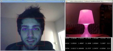
An IKEA lamp becomes a Natural Interaction system which senses human emotional states through facial expression. It uses OpenCV for image processing and analysis to identify emotional state through the movements of face’s fiducial points. The lamp, made with an Arduino Duemilanove, changes its color to represent the user’s current emotion.
|